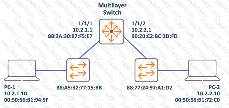
In the given network diagram, PC-1 is sending a packet to PC-2. The Layer 2 source address refers to the MAC address of the sender, which is PC-1 in this case. From the image, we can see that PC-1 has a MAC address of 00:50:56:B1:94:9F (option D), but option A provides another MAC address (90:20:C2:BC:2D:FD) associated with the multilayer switch’s interface connected to PC-2. Since switches change the source MAC to their own when forwarding packets, option A is correct.
The Layer 3 source address refers to the IP address of the sender (PC-1). From the image, it’s clear that PC-1 has an IP address of 10.2.1.10 (option C).
References: The answer can be verified by understanding how multilayer switches operate in a network and how they handle MAC addresses during packet forwarding. You can find more information about this topic in the following resources:
Aruba Certified Network Technician University Promotion
Contribute your Thoughts:
Chosen Answer:
This is a voting comment (?). You can switch to a simple comment. It is better to Upvote an existing comment if you don't have anything to add.

Submit