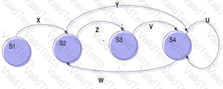
In state transition testing, test cases are designed to execute specific sequences of state transitions. Referring to the provided state transition diagram:
For test case (i) X-Z-V-W, the corresponding state transitions are S1 (X) → S2, S2 (Z) → S3, S3 (V) → S4, and S4 (W) → S2. Therefore, the sequence of state transitions is S1 – S2 – S3 – S4 – S2.
For test case (ii) W-Y-U-U, the corresponding state transitions are S4 (W) → S2, S2 (Y) → S4, S4 (U) → S4, and S4 (U) → S4. Therefore, the sequence of state transitions is S4 – S2 – S4 – S4 – S4.
This ensures that the transitions accurately reflect the states and paths described in the test cases.
[Reference: ISTQB CTFL Syllabus, version 4.0, provides guidelines on state transition testing and mapping test cases to state transitions., ]
Contribute your Thoughts:
Chosen Answer:
This is a voting comment (?). You can switch to a simple comment. It is better to Upvote an existing comment if you don't have anything to add.

Submit